4 Circuits
- Circuits (in this simple case) can be high (VCC), low (GND), or floating. It's the same voltage throughout (5V).
- The controller has GPIOs (General Purpose Input Output pins).
- Output pins are set to high or low.
- Input pins are internally pulled high with a resistor or left floating.
- This creates a "weak" logic value that can be overrun by a direct connection.
- Back to mechanical keyboards, most switches will create a connection between two contacts when pressed.
- So an input pin pulled high will read high unless the switch (connected to GND) is pressed.
- The Pro Micro has 21 GPIOs, which is enough for 21 inputs (thus 21 switches), unless we use a key matrix.
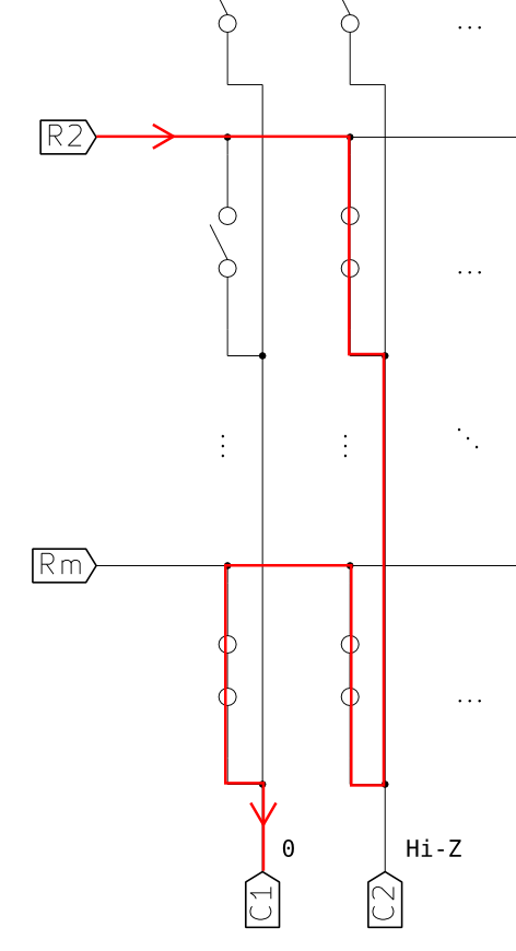
- Connect each row and each column to a pin.
- Set all the rows to be high outputs.
- Set all the columns to be pulled high inputs.
- Set one row to low and check the column pins.
- If a column pin is low you know that switch is pressed.
- Check the next row and repeat.
Image Credit

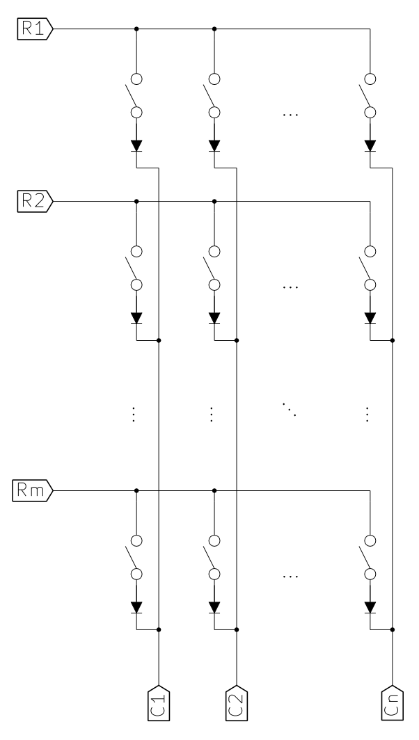
- Only let current flow one way: from anode to cathode. The black end of the diode is the cathode.
- Used to prevent ghosting (when a switch appears pressed when it isn't).
- LEDs actually work like diodes (Light Emitting Diodes).
- The longer lead is the anode, so the positive voltage must be applied there.
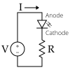
- They will eat up all the current and burn out, so you must add a resistor to limit it.
- Here's what the circuit looks like:
Image Credit
- Turn the multimeter to the Ω (ohm) symbol. This will set the multimeter to display the resistance between the two leads. If there is no continuity it will display OL (Open Loop) or something similar.
- Try tapping the black and red leads together. The reading should become 0Ω.
- You can also do this at two ends of a circuit, and if it reads 0Ω you know they're continuous.
- For a diode, because current flows from the red lead (VCC) to the black lead (GND), the meter will only display continuity for one direction (red at the anode and black at the cathode).