2 Plate
We will be making plates from acrylic.
- Log into one of the lab computers and open the program "Solid Edge".
- Create a new "ANSI Draft".
- Click the orb in the upper left, and go to Settings > Sheet setup. Change the size to "B Wide" and uncheck "Show background".
- Save you file. Call it something similar to "YOURNAME - Plate".
- You are now ready to start. Get a calculater and get your layout ready on Keyboard Layout Editor so you can calculate the key-size and key-spacing. (1u = 0.75").
- Here are some general measurements:
| Part | Dimensions |
|---|---|
| Switch Cutout | 0.551" x 0.551" |
| 1u Switch Spacing | 0.75" x 0.75" (from center to center) |
| Recommended Outside Margin | 0.4" |
| Screw Hole Radius | 0.039" |
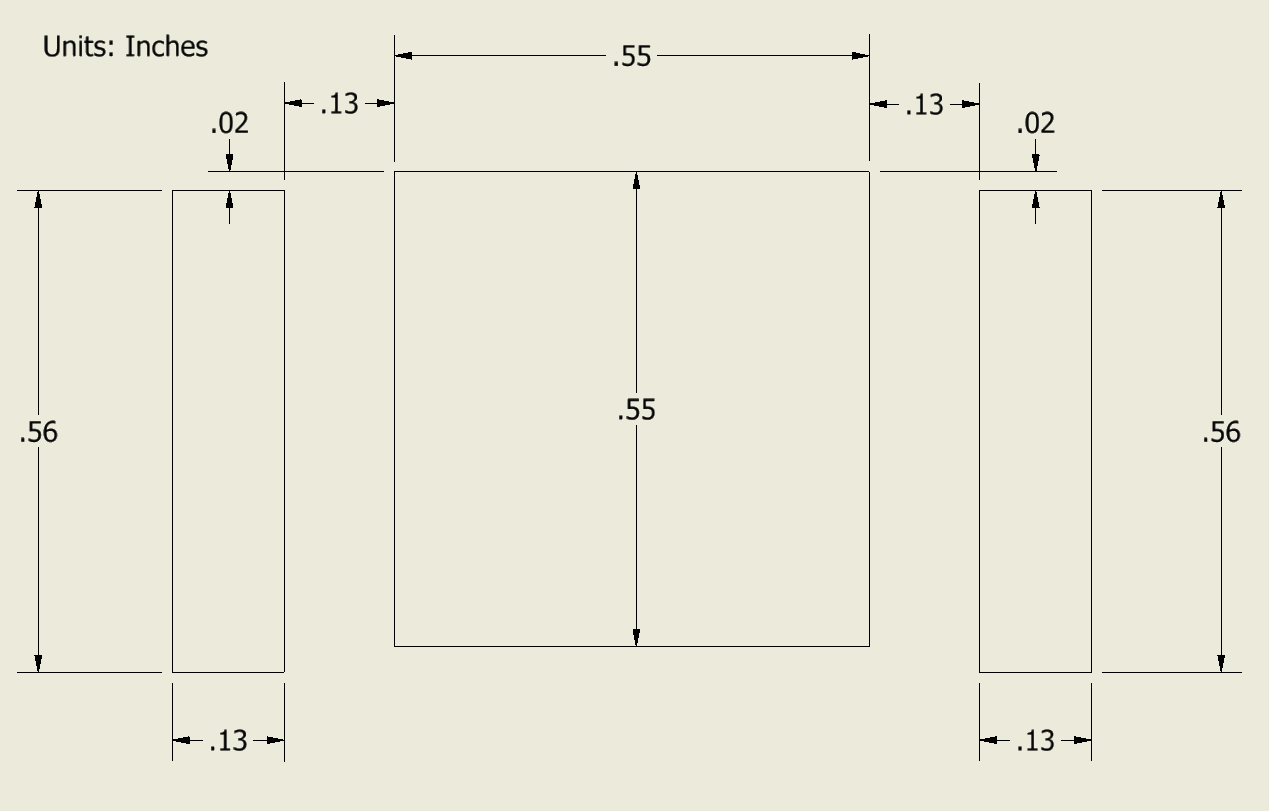
Dimensions of a standard stabilizer (2u ≤ key-size ≤ 3u).
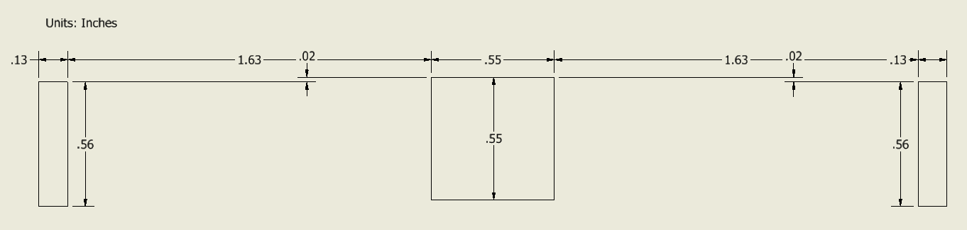
Dimensions of a spacebar stabilizer (6.25u)
- Here is an example of numberpad's top plate. The purple lines should not be there on the final draft, and are just shown to demonstrate the spacing. Purple is key spacing, green is switch cutouts, blue is the outline, and yellow are the screw holes.

- Email me your plate file so I can download them onto the computer connected to the laser cuter.
- I'll just show you what to do.