
A simple logic analyzer application for the DSO Quad (aka DS203) pocket oscilloscope.
See this blog post for more information and also the wiki
- It allows to write signals continuously into DSO internal flash drive in background using either VCD or RAW format. This makes possible to store up to 8MB of events (i.e. about 8 million signal transitions).
- It allows to select input voltage range for channels A and B. This makes possible to analyze lower and higher (than TTL) voltage interfaces.
- It allows to enable and control DSO internal signal generator ("Wave Out port") during signal capture. This gives you a chance to check your DSO logic analyzer functions and use it as a clock source for your circuits.
- RAM buffer which is allocated to be "visible" on the screen is about three times smaller than that for the original app (7K vs 20K, it is a trade off for background flash drive data writing).
New settings menu looks like following
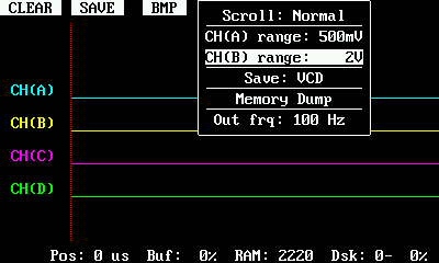
Use < and > ("Navigation") rotating switch to select menu item. Use - and + rotating switch to change item value. White menu color means that the selected value is the current active one. Grey color means the selected value is not applied yet. To apply/save selected value press "Navigation" rotating switch.
CH(A/B) range allows to select input channels A and B voltage range
Save allows to select format of data to be written: VCD or RAW (see below)
Memory Dump creates (surprise!) memory dump for debugging purposes
Out frq allows to control internal signal generator ("Wave Out port") frequency
Data formats:
VCD is ready to be used by many signal analyzing applications. DS203 v2.7 flash drive (8MB) is capable to accept less than 1000 signal transitions/sec and is big enough to keep about 3 minutes of events at that rate
RAW allows to cope with about 3000 signal transitions/sec and to keep about 11 minutes of events at that rate. Yet you have to use decode-raw.py application to convert RAW data into VCD
During the normal operations:
First (counting from the left side, usually marked as ||> or play/pause) button clears RAM buffer and restarts data capture (and interrupts signal storing to the flash drive if it is currently running).
Second ([] or square or stop) button starts (if not yet running) or stops (if write is ongoing) data capture to the flash drive.
Background data writing is implemented using double buffering approach. There are two RAM buffers allocated. Only the first one is attached to a viewport. Both of them are used to capture data events and to store data to the flash disk one after another.
The new status line meaning:
Pos shows the current displayed position in a first RAM buffer
Buf shows how much of the active RAM buffer is filled up with data
RAM shows the remaining application RAM size
Dsk shows disk write status. First digit is the active buffer (0 - first, 1 - second). Second character is the disk write status: '-' writing is not active. '@' writing is activated. 'W' writing is ongoing. The last number is the amount of data written to the flash disk related to the disk size since the app start. Beware, that DSO API does not provide application with actual disk free size and this number is just a rough estimation only for the current session, assuming that the disk was empty at start.
P.S. The particular binary LOGICAPP.HEX is built using gcc-arm-none-eabi-4_7-2014q2 toolchain and tested using DS203 HW2.72 with 8MB flash.
P.P.S. It is strictly recommended to update your device with AlterBIOS 1.64 from Petteri Aimonen to avoid constant filesystem crashes.
P.P.P.S. Many thanks to Petteri Aimonen for his kind assistance in finding proper build toolchain.