

The Quad Display Board features four displays in a single board Powered by ESP32 S3 WROOM-1, offering unparalleled flexibility and functionality for your creative endeavors. With options for both a 1.28" Round Display and a 1.54" Square Display, you have the freedom to choose the perfect size for your project needs.
This Github provides getting started instruction for 2x2 Display with ESP32.
- Powered by ESP32 S3 which is having Dual-core Arm Cortex-M0+ processor, running up to 133 MHz
- Four Square/Round Display in 2x2 arrangement for creative visual interactions
- Both Serial and Native USB available as Type C
- DS3231 RTC for real-time capture and control activity With Backup Battery Holder
- BME280 Sensor for temperature, humidity and pressure monitoring
- Power and Charging LED for status indication
- Battery hookup and charging facilities for portability
- Onboard microSD card compatibility is useful for data logging purposes
- Multipurpose GPIOs breakout for additional peripheral interfacing
- Boot and Reset Buttons for programming purpose
- Two Programmable Buttons to add additional controls to project
- Buzzer which helps to add audio alert for your project
- Microcontroller: ESP32 S3 WROOM-1, Xtensa® dual-core 32-bit LX7 microprocessor
- Connectivity: 2.4 GHz Wi-Fi (802.11 b/g/n) and Bluetooth® 5 (LE)
- Memory: Flash up to 16 MB, PSRAM up to 8 MB
- Supply Voltage: 5V
- Operating pin voltage: 3.3V
- Display:
- Display Size: 1.54” (Square), 1.28” (Round)
- Display Type: IPS TFT
- Display Resolution: 240 x 240 pixels
- Display colors: 65K RGB
- Display interface: SPI
- Display Driver: ST7789V (Square), GC9A01A (Round)
- Sensor: BME280 for Temperature, Pressure & Relative Humidity
- RTC Chip: DS3231SN
- RTC Battery Holder: Supports CR1220 3V Battery
- Operating Temperature Range: -20°C ~ +70°C

-
Display interfacing with ESP32
ESP32 Display Function IO12 LCD1_CLK Clock pin of SPI interface for Display IO11 LCD1_DIN MOSI (Master OUT Slave IN) pin of SPI interface IO9 LCD1_CS Chip Select pin of SPI interface IO13 LCD1_DC Data/Command (MISO) pin of SPI interface IO45 LCD_BL Backlight of display ESP32 Display Function IO15 LCD2_CLK Clock pin of SPI interface for Display IO6 LCD2_DIN MOSI (Master OUT Slave IN) pin of SPI interface IO21 LCD2_CS Chip Select pin of SPI interface IO7 LCD2_DC Data/Command (MISO) pin of SPI interface IO45 LCD_BL Backlight of display ESP32 Display Function IO14 LCD3_CLK Clock pin of SPI interface for Display IO8 LCD3_DIN MOSI (Master OUT Slave IN) pin of SPI interface IO48 LCD3_CS Chip Select pin of SPI interface IO47 LCD3_DC Data/Command (MISO) pin of SPI interface IO45 LCD_BL Backlight of display ESP32 Display Function IO18 LCD4_CLK Clock pin of SPI interface for Display IO16 LCD4_DIN MOSI (Master OUT Slave IN) pin of SPI interface IO10 LCD4_CS Chip Select pin of SPI interface IO17 LCD4_DC Data/Command (MISO) pin of SPI interface IO45 LCD_BL Backlight of display -
SDcard Interface
ESP32 SDCard Function IO42 CARD_CLK Clock pin of SPI interface for Display IO2 CARD_MOSI MOSI (Master OUT Slave IN) pin of SPI interface IO41 CARD_MISO MISO (Master IN Slave OUT) pin of SPI interface IO1 CARD_CS Chip Select pin of SPI interface
-
BME280 & DS3231 RTC I2C Interfacing
ESP32 Hardware Hardware Function IO39 BME280_SCL RTC_SCL I2C Serial Clock IO38 BME280_SDA RTC_SDA I2C Data pin -
Buttons & Buzzer Interfacing
ESP32 Hardware Function IO0 BOOT Boot button IO4 BT1 Programmable Button IO5 BT2 Programmable Button IO40 Buzzer Buzzer control pin -
GPIOs Breakout
ESP32 Type* Multi-Function (Bold-Italic default Function) 3V3 P Positive Supply, 3.3V IO3 I/O/T RTC_GPIO3, GPIO3, TOUCH3, ADC1_CH2 IO46 I/O/T GPIO46 GND P Supply Ground *I-INPUT, O-OUTPUT, P-POWER & T-HIGH IMPEDENCE
-
Download Arduino IDE from official site and install into your system. We have use Arduino IDE 1.8.19
-
Once installation done will add ESP32 S3 board support into IDE, for this first you need to add below link into preference:
https://raw.githubusercontent.com/espressif/arduino-esp32/gh-pages/package_esp32_index.jsonSelect File > Preference, and add link as show in below image,

-
Now will install ESP32 based boards as shown in below image,

-
You have two options to program onboard ESP32 of 2x2 display board, UART USB OR Native USB.
-
When using Native ESP USB, you will have to press BOOT button once and then connect Type C. For UART USB no need, directly connect USB.

-
Once done (for UART USB), keeping default settings select the ESP32S3 Dev Module with suitable COM PORT (may be different in your case) as shown below,

You can view assigned COM port through Device Manager,

-
When using USB native you will get COM PORT as shown in below image, and while uploading you can enable CDC Mode to visualize data on serial com port.


-
Download library zip file provided here in github.
-
Extract and copy files inside Document > Arduino > Libraries folder. Make sure to restart Arduino IDE whenever you update or add any libraries.


- At this step you are all set to test codes, for easy getting started we have provided various demo example codes in github which you can download and try.
- Make sure to use relevant example code for your specific board:
- Open one example code in Arduino and make sure you have selected correct board with suitable com port, click on upload button to transfer code on ESP32 of 2x2 Display board.

- Checkout other reference examples, modify, build and share!

- Schematic
- Hardware Files
- Step File
- Getting Started with ESP32 in Arduino
- ESP32 S3 Hardware Reference
- ESP32 S3 Datasheet
- Arduino IDE 1 overview
-
2x2 Display with Pico W (Round)
-
2x2 Display with Pico W (Square)
-
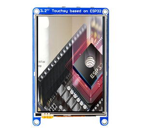
Touchsy - 3.2" Touch LCD Display Based on ESP32
-
Rotary Encoder - LED Array & Touch LCD Powered by ESP32



This is open source product. Kindly check LICENSE.md file for more information.
Please contact support@sb-components.co.uk for technical support.
