NES Controller Turbofire Extension by RetroCityRansom


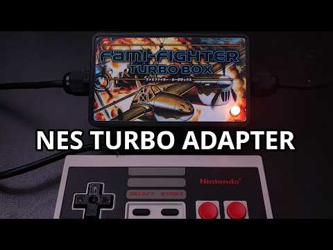
The "Fami-Fighter Turbo Box" is a solution for adding turbo-fire functionality to NES controllers at several selectable, preset speeds. Instead of modifying the controller itself, a small box containing an Arduino is simply connected between the controller and the NES or AV Famicom via an extension cable; this box then alters the controller signal according to the chosen turbo settings. The project is designed to use only a few electrical components and requires only minimal soldering. I have tested the box with a wide variety of games, including "Castlevania III" and "Journey to Silius," as these titles can sometimes be problematic when processing signals from DIY controllers.
Watch the teaser on Youtube
Yes and no. Different games benefit from different autofire speeds, but if you're using for instance a Nintendo Four Score adapter or the 8BitDo N30 controller for turbo, the autofire rate is fixed and can't be adjusted. The NES Advantage arcade stick, on the other hand, lets you dial in the turbo speed to whatever works best for the game. But what if you simply want to use a standard NES controller, a PlayStation controller, or a proper arcade stick through a Bluetooth adapter such as the RetroReceiver?
I found a solution on YouTube, but it seemed a bit too advanced for beginners and unnecessarily complicated. It had it's own advantages, though. If you're primarily a gamer (like me) and only do a bit of soldering from time to time, you probably want a simple, inexpensive solution that doesn't require modifying your original controller, still lets you use wireless adapters, and can be built in just a few minutes.
That was exactly the goal of this project—so here it is: the Turbo Box.
- Very easy to build
- Separate turbofire toggle for buttons A and B via hotkey combination
- Selectable autofire speed via hotkey combination
- Optional NEOPIXEL LED support to visualize, if turbofire is active and at which speed
- Easy to extend - change LED colors, use an OLED instead of the LED, add / change turbofire frequencies as required
- Compatible with the Nintendo Four Score
- Compatible with the SN30 2.4Ghz controller and Retroreceiver
- Acts of course as a cable extension
- Tested with several different controllers
- It could benefit from a hardware extension (similar to SNEngine) to behave more like 'real' hardware for timing-critical games. However, a friend of mine tested the box with Punch-Out!! and made it all the way to Mike Tyson without any issues.
- Not for people, who want a more advanced soldering project.
- SELECT + UP: Increase turbofire speed (LED colour becomes more intensive; if pressed when the highest frequency was already active, the cycle goes back at the lowest frequency)
- SELECT + DOWN: Decrease turbofire speed (LED colour becomes less intensive; if pressed when the lowes frequency was already active, the highest freqency will be set active)
- SELECT + RIGHT: (De)Activate turbofire for button A
- SELECT + LEFT: (De)Activate turbofire for button B
- If no turbo is activated, the LED glows green.
- If both turbos (A+B) are activated, the LED glows purple.
- If Turbo has been activated for button A, the LED has blue tone (or white, in the lowest frequency setting).
- If Turbo has been activated for button B, the LED's color ranges between yellow and red.
- The faster the selected turbofire speed, the more intensive the LED will glow.
Power supply: Please make sure that your power supply is adequately rated. In my testing, a 1.5 A power supply was sufficient to run two TBs with two 8BitDo N30 gamepads and two original NES controllers connected to a Four Score while using an Everdrive N8 Pro at the same time. Smaller power supplies may also work, but this has not been tested.
Warning: Never connect two or more Turbo Boxes together. A Turbo Box must only be connected directly to the console or the multiplayer adapter.
Use at your own risk. I am not an electrician and strongly advise against trying this without consulting a qualified professional and verifying the accuracy of all information provided in this repository. The adapter has not been thoroughly tested yet. You may need to add resistors, capacitors or other electrical parts to ensure safe and error free operation. The pictures provided here are not an implementation manual, but rather a personal photo diary.
- 1 × Arduino Pro Mini
- 1 × NES extension cable
- The code from this repository
- The usual soldering equipment, cables, heat shrink tubes
- 1 x 10 kΩ resistor required as pullup for console latch -> otherwise the Turbo Box will not work with a Four Score if not at least a second original NES controller has been plugged in
If that won't work for you, you can also add a 10k pullup to the Ardu's console clock pin.
- 1 x Neopixel RGB LED -> to indicate the chosen turbo speed and if turbo is inactive or active for A, B or both buttons
- 1 × 10-position screw terminal block for Arduino
- 1 × 12-position screw terminal block for Arduino
- 1 x Schottky Diode (BAT85) -> add between Famicom/NES +5V line and Arduino VCC pin to protect the console
- 1 x 100 nF ceramic capacitor -> add between Arduino VCC and GND pin
- 1 x 100 µF electrolytic capacitor next to the Ardu or between the GND and VCC rails, if you have them. Absolutely recommended, if you plan to use Bluetooth or 2.4 GHz adapters with the Turbo Box
- 2 x 100 Ω resistors -> add one between console and Arduino in data line; add the other to the data line of the LED
- Some printable sticker paper for stickers!! :-)
- 1 x small perfboard
- 2 x 4 or 6-position screw terminal block
- a few wire leades taken from a resistor, if available
- 1 x DIY box, e.g. like THESE (I have tried these and they are okay with just a small caveat) or maybe THESE
- 2 x PG-7 cable gland / strain relief

| Side A | Wire | Side B | Notes |
|---|---|---|---|
| gamepad | Clock | Ardu D3 | |
| gamepad | Latch | Ardu D4 | |
| gamepad | Data | Ardu D5 | |
| gamepad | +5V | VCC rail | |
| gamepad | GND | GND rail | |
| console | Clock | Ardu D12 | |
| console | Latch | Ardu D9 | |
| console | Data | Ardu D11 | insert 100 Ω resistor |
| console | +5V | VCC rail | insert Schottky diode (e.g. Bat-85); kathode points to Arduino |
| console | GND | GND rail | |
| Neopixel LED | Data | Ardu A3 | insert 100 Ω resistor |
| Neopixel LED | +5V | VCC rail | |
| Neopixel LED | GND | GND rail |
- Add 100 nF ceramic capacitor between GND and VCC of Arduino
- Add 100 µF electrolytic capacitor between GND rail and VCC rail; mind the polarity
- Add a 10 kΩ pullup resistor between D9 (console latch) and VCC for increased Four Score compatibility
Drill a hole for the PG7 cable glands in each side of the box. Use a dry-erase marker or remove the ink with isopropyl alcohol after drilling.

Gradually enlarge the opening until you can screw in the PG-7 securely without having to use the PG7's nut, but finally tighten it.


If you want to install the RGB LED later, make a small 5-6mm hole in the lid.

If you plan to use a ground rail and a 5V rail, which is highly recommended, then prepare a small piece of perfboard. I prefer using screw terminals here for easier handling and later modifications.
Also add a 100 µF electrolytic cap to the board. I did this after some testing, as you will see later.


I connect the pins of each rail using two legs that I cut off from an old resistor.


- Then the NES controller extension cable is cut in the middle and the ends are stripped.
- I extend the small wires with wires of the same color and, solder on a Schottky diode (+5V) or an 100 Ω resistor (data line).
- The solder joints and the soldered electronic components are protected with heat-shrink tubing.
- For example, in the extension cable I used here, the +5V cable was blue and the ground cable was green.

My data cable turned out to be red, and here I soldered a 100 Ω resistor into the wire coming from the console.

I didn't solder any resistors or anything similar to the wires that go to the gamepad, I just extended them.

- Because I'm lazy, I'm also using screw terminals on the Arduino. If I need the Arduino for something else later, or if I made a mistake with the wiring, I can simply unscrew the cables.
- Don't forget to flash the software before using the Ardu.


I prefer not to cut off unused wires, but rather fix them to the main cable using heat shrink tubing.


Preparing the Neopixel LED...


Okay, now all the wires are just slapped on. This is now very quick, because of the screw terminals.


And that's nearly it... I added a 100 nF ceramic capacitor to the Arduino afterwards and made some more additions, as you will see.

After some testing, I've decided to add a 100 µF electrolytic capacitor to the rail board.

Some antistatic tape for isolation ...

Another late addition. To make the Turbo Box work on a Four Score adapter, I've added a 10kΩ resistor as pullup to the console latch pin of the Arduino (between Ardu console latch pin and VCC rail). If that should not work out for you, there's also still the option to do the same for console clock and console data, but it was not necessary in my cases.

Bam, there it is. The LED glows green when turbo fire is not activated.

Blue indicates that turbo is activated for button B ...

...and yellow/orange/red indicates turbo fire for A.

The rule is always: the faster the turbo firing speed, the more intense the color of the LED.

If turbo fire is activated for A and B simultaneously, it glows purple.

Added a finishing by printing out stickers on photo sticker paper.


Thank you, good night. See you at the bar :-)