8bit TFT Library for Arduino_Core_STM32(ST Core)
I ported from here.
https://github.com/prenticedavid/MCUFRIEND_kbv
- ILI9325 2.4inch 240x320 TFT-Shield
- ILI9341 2.4inch 240x320 TFT-Shield
- ILI9342 2.4inch 240x320 TFT-Shield
- SPFD5408 2.4inch 240x320 TFT-Shield
- R61505 2.4inch 240x320 TFT-Shield
- ST7783 2.4inch 240x320 TFT-Shield
- LGDP4532 2.4inch 240x320 TFT-Shield
- R61509V 3.6inch 240x400 TFT-Shield
- ST7793 3.6inch 240x400 TFT-Shield
- ILI9481 3.5inch 320x480 TFT-Shield
- ILI9486 3.5inch 320x480 TFT-Shield
- RM68140 3.95inch 320x480 TFT-Shield
- ST7796 3.95inch 320x480 TFT-Shield
I found that these display cannot follow high-speed GPIO-ON and GPIO-OFF.
- OPEN-SMART ILI9225 TFT-Shield
- OPEN-SMART ILI9327 TFT-Shield
- OPEN-SMART ILI9340 TFT-Shield
- OPEN-SMART S6D1121 16Pin-Parallel
- OPEN-SMART ST7775 16Pin-Parallel
- OPEN-SMART ST7783 16Pin-Parallel
- OPEN-SMART R61509V 16Pin-Parallel
- OPEN-SMART ILI9488 16Pin-Parallel

This library uses LL GPIO Generic Driver and CMSIS ODR Register.
Probably all boards have these available.
I tested on these.
- STM32F0/F1/F3/F4 series
- STM32G0/G4 series
- STM32H5 series
- STM32L4 series
-
Arduino IDE
I used V1.8.19

-
Arduino core support for STM32 based boards
https://github.com/stm32duino/Arduino_Core_STM32
Note for Core version
Core version 2.8 or later requires Arduino IDE 2.x.
I used version 2.7.1.
This is the final version available for Arduino IDE 1.x.
There is some core library for STM32.
It doesn't work with Arduino STM32.
-
STM32 Cube Programmer
The Arduino IDE uses the STM32CubeProgrammer to write firmware to the STM32.
Please note that older versions of STM32CubeProgrammer do not support newer models such as STM32G0.
I used version 2.20.

-
Adafruit GFX Library
https://github.com/adafruit/Adafruit-GFX-Library
I used version 1.11.9.


| TFT | STM32 | |
|---|---|---|
| LCD_RD | -- | PB0(*1) |
| LCD_WR | -- | PB1(*1) |
| LCD_RS | -- | PB5(*1) |
| LCD_CS | -- | PB6(*1) |
| LCD_RST | -- | PB7(*1) |
| LCD_D0 | -- | PA0(*2) |
| LCD_D1 | -- | PA1(*2) |
| LCD_D2 | -- | PA2(*2) |
| LCD_D3 | -- | PA3(*2) |
| LCD_D4 | -- | PA4(*2) |
| LCD_D5 | -- | PA5(*2) |
| LCD_D6 | -- | PA6(*2) |
| LCD_D7 | -- | PA7(*2) |
| 5V | -- | 5V(*3) |
| 3.3V | -- | 3.3V(*3) |
| GND | -- | GND |
(*1)
You can change to other PB pin.
To change the pin, change Arduino-STM32-8bitTFT.h.
Some boards assign PB3 and PB4 to the JTAG debug port by default.
Therefore, depending on the board, PB3 and PB4 may not be available as GPIO.
These GPIO are controlled using LL_GPIO_WriteOutputPort().
#define TFT_CNTRL      GPIOB

#define TFT_RD         LL_GPIO_PIN_0 // PB0
#define TFT_WR         LL_GPIO_PIN_1 // PB1
#define TFT_RS         LL_GPIO_PIN_5 // PB5
#define TFT_CS         LL_GPIO_PIN_6 // PB6
#define TFT_RST        LL_GPIO_PIN_7 // PB7
These GPIOs can be changed to PC ports.
//#define TFT_CNTRL      GPIOB
#define TFT_CNTRL      GPIOC

#define TFT_RD         LL_GPIO_PIN_0 // PC0
#define TFT_WR         LL_GPIO_PIN_1 // PC1
#define TFT_RS         LL_GPIO_PIN_5 // PC5
#define TFT_CS         LL_GPIO_PIN_6 // PC6
#define TFT_RST        LL_GPIO_PIN_7 // PC7
These GPIOs can be changed to PD ports.
//#define TFT_CNTRL      GPIOB
#define TFT_CNTRL      GPIOD

#define TFT_RD         LL_GPIO_PIN_0 // PD0
#define TFT_WR         LL_GPIO_PIN_1 // PD1
#define TFT_RS         LL_GPIO_PIN_5 // PD5
#define TFT_CS         LL_GPIO_PIN_6 // PD6
#define TFT_RST        LL_GPIO_PIN_7 // PD7
(*2)
The output destination of Serial.print conflicts with these GPIOs.
The output destination of Serial.print differs depending on the Board Part Number.
- F103 BluePill:PA9
- F103 BlackPill:PA9
- Generic F103:PA2
- NUCLEO and DISC1:PA2
- Generic STM32G series:PA2
- Generic STM32H series:PA0
You will need to do one of the following:
- Change D0 to D7 to another GPIO
- Change default Serial instance pins
To change the GPIOs for LCD_D0 to D7, modify Arduino-STM32-8bitTFT.h.
D0 to D7 are controlled using CMSIS ODR Register.
This register can change multiple IOs at once, but only IOs on the same port.
Therefore, D0 to D7 must be the same port.
If PORT-A is used for D0-D7, all GPIOs on PORT-A cannot be used for other purposes.
Because CMSIS ODR Register manipulates all GPIOs of PORT-A.
GPIOA->ODR = 0x00FF
This code not only sets D0 to D7 of PORT-A to 1, but also sets D8 to D15 of PORT-A to 0.
You can use any of the following:
- PORT-A LOW
TFT Pin|D7 |D6 |D5 |D4 |D3 |D2 |D1 |D0 |
STM32 Pin|PA7|PA6|PA5|PA4|PA3|PA2|PA1|PA0| - PORT-A HIGH
TFT Pin|D7 |D6 |D5 |D4 |D3 |D2 |D1 |D0 |
STM32 Pin|PA15|PA14|PA13|PA12|PA11|PA10|PA9|PA8| - PORT-C LOW
TFT Pin|D7 |D6 |D5 |D4 |D3 |D2 |D1 |D0 |
STM32 Pin|PC7|PC6|PC5|PC4|PC3|PC2|PC1|PC0| - PORT-C HIGH
TFT Pin|D7 |D6 |D5 |D4 |D3 |D2 |D1 |D0 |
STM32 Pin|PC15|PC14|PC13|PC12|PC11|PC10|PC9|PC8| - PORT-D LOW
TFT Pin|D7 |D6 |D5 |D4 |D3 |D2 |D1 |D0 |
STM32 Pin|PD7|PD6|PD5|PD4|PD3|PD2|PD1|PD0| - PORT-D HIGH
TFT Pin|D7 |D6 |D5 |D4 |D3 |D2 |D1 |D0 |
STM32 Pin|PD15|PD14|PD13|PD12|PD11|PD10|PD9|PD8|
The STM32 can use multiple GPIOs as serial ports.
For example, on BluePill/BlackPill, the following GPIOs can be used as serial ports:
//*** UART ***

WEAK const PinMap PinMap_UART_TX[] = {
  {PA_2,  USART2, STM_PIN_DATA(STM_MODE_AF_PP, GPIO_PULLUP, AFIO_USART2_DISABLE)},
  {PA_9,  USART1, STM_PIN_DATA(STM_MODE_AF_PP, GPIO_PULLUP, AFIO_USART1_DISABLE)},
  {PB_6,  USART1, STM_PIN_DATA(STM_MODE_AF_PP, GPIO_PULLUP, AFIO_USART1_ENABLE)},
  {PB_10, USART3, STM_PIN_DATA(STM_MODE_AF_PP, GPIO_PULLUP, AFIO_NONE)},
  {NC,    NP,     0}
};

WEAK const PinMap PinMap_UART_RX[] = {
  {PA_3,  USART2, STM_PIN_DATA(STM_MODE_INPUT, GPIO_PULLUP, AFIO_USART2_DISABLE)},
  {PA_10, USART1, STM_PIN_DATA(STM_MODE_INPUT, GPIO_PULLUP, AFIO_USART1_DISABLE)},
  {PB_7,  USART1, STM_PIN_DATA(STM_MODE_INPUT, GPIO_PULLUP, AFIO_USART1_ENABLE)},
  {PB_11, USART3, STM_PIN_DATA(STM_MODE_INPUT, GPIO_PULLUP, AFIO_NONE)},
  {NC,    NP,     0}
};
The example below uses PB10/PB11 as a Serial Object.
  Serial.setTx(PB10); // TX
  Serial.setRx(PB11); // RX
  Serial.begin(115200);
GPIO that can be used as a Serial object differs depending on the MCU.
You can know which GPIOs can be used in PeripheralPins.c of the MCU.
PeripheralPins.c is here.
(*3)
When a regulator(It's often AMS1117) is mounted on the back, it's operated 5V.
When a regulator is NOT mounted on the back, it's operated 3.3V.
Note:Keep the wire length as short as possible.
The default resolution of this library is 240x320.
If your TFT's resolution is 320x480,
you have to set your TFT's resolution using tft.setResoution.
ID = tft.readID();
tft.setResolution(320, 480); // Set your resolution
Serial.print("Device ID: 0x"); Serial.println(ID, HEX);
tft.begin(ID);
uint32_t width = tft.width();
Serial.print("Width: "); Serial.println(width); // You will see 320
uint32_t height = tft.height();
Serial.print("Height: "); Serial.println(height); // You will see 480
If your TFT's resolution is 240x400,
you have to set your TFT's resolution and TFT's offset.
ID = tft.readID();
tft.setResolution(240, 400); // Set your resolution
tft.setOffset(32); // Set your offset
Serial.print("Device ID: 0x"); Serial.println(ID, HEX);
tft.begin(ID);
uint32_t width = tft.width();
Serial.print("Width: "); Serial.println(width); // You will see 240
uint32_t height = tft.height();
Serial.print("Height: "); Serial.println(height); // You will see 400
-
STM32F103 + R61505 2.4 inch TFT
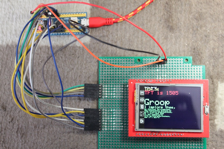
-
STM32F103 + SPFD5408 2.4 inch TFT

-
STM32F103 + ILI9325 2.4 inch TFT

-
STM32F103 + ILI9341 2.4 inch TFT

-
STM32F103 + ILI9342 2.4 inch TFT

-
STM32F401 + ILI9341 2.4 inch TFT

-
STM32F407 + ILI9341 2.4 inch TFT

-
NUCLEO F446RE + ILI9341 2.4 inch TFT (Use PC0-PC7 for D0-D7)

-
STM32G030 + ILI9341 2.4 inch TFT

-
STM32G431 + ILI9341 2.4 inch TFT

-
STM32H750 + ILI9341 2.4 inch TFT (Use PC0-PC7 for D0-D7)

The control ports (RD/WR/RS/CS/RST) are switched on/off using the LL_GPIO_WriteOutputPort function.
Instead of using the LL_GPIO_WriteOutputPort function, you can use the Port bit set/reset register.
//#define CNTL_INTERFACE 0 // The control port uses the LL_GPIO_WriteOutputPort function
#define CNTL_INTERFACE 1 // The control port uses Port bit set/reset (BSRR) Register
This option speeds up the display.
It may not work on high-speed Valiant boards such as the F407 and F446.
Furthermore, the wire cables must be as short as possible.
The unit is microseconds.
-
Valiant is Generic F103. CPU Frequency is 64MHz.
Options CNTL_INTERFACE 0 CNTL_INTERFACE 1 Screen fill 793547 468909 Text 65602 43645 Lines 617476 392079 Horiz/Vert Lines 66107 39275 Rectangles (outline) 43226 25888 Rectangles (filled) 1647687 973586 Circles (filled) 236781 148907 Circles (outline) 272475 173902 Triangles (outline) 136929 86731 Triangles (filled) 572235 344905 Rounded rects (outline) 111681 70286 Rounded rects (filled) 1653430 979834 -
Valiant is F103 PillBoard. CPU Frequency is 72MHz.
Options CNTL_INTERFACE 0 CNTL_INTERFACE 1 Screen fill 705234 416759 Text 58300 38791 Lines 548765 348480 Horiz/Vert Lines 58750 34907 Rectangles (outline) 38415 23009 Rectangles (filled) 1464352 865322 Circles (filled) 210432 132348 Circles (outline) 242155 154560 Triangles (outline) 121691 77088 Triangles (filled) 508563 306550 Rounded rects (outline) 99252 62469 Rounded rects (filled) 1469446 870876 -
Valiant is BlackPill F401CC. CPU Frequency is 84MHz.
Options CNTL_INTERFACE 0 CNTL_INTERFACE 1 Screen fill 247241 192333 Text 26177 20430 Lines 240153 177725 Horiz/Vert Lines 20854 16212 Rectangles (outline) 13871 10792 Rectangles (filled) 513445 399455 Circles (filled) 84325 65780 Circles (outline) 105621 78305 Triangles (outline) 52836 39184 Triangles (filled) 186336 145204 Rounded rects (outline) 41465 31279 Rounded rects (filled) 518461 403446 -
Valiant is BlackPill F411CE. CPU Frequency is 100MHz.
Options CNTL_INTERFACE 0 CNTL_INTERFACE 1 Screen fill 216318 168281 Text 22914 17914 Lines 209843 155334 Horiz/Vert Lines 18245 14185 Rectangles (outline) 12137 9445 Rectangles (filled) 449223 349489 Circles (filled) 73813 57629 Circles (outline) 92305 68411 Triangles (outline) 46180 34295 Triangles (filled) 163041 127048 Rounded rects (outline) 36258 27380 Rounded rects (filled) 453632 353008
The unit is microseconds.
I used the LL_GPIO_WriteOutputPort function to turn the control port on and off.
| Valiant | F072 | F103(Generic) | F103(PillBoard) | F303 | F401 | F411 | F407 | F446 | G030 | G431 | H750 | L452 | ATmega328 |
|---|---|---|---|---|---|---|---|---|---|---|---|---|---|
| CPU Freq | 48MHz | 64MHz | 72MHz | 72MHz | 84MHz | 100MHz | 168MHz | 180MHz | 64MHz | 170MHz | 480MHz | 80MHz | 20MHz |
| Core | M0 | M3 | M3 | M4 | M4 | M4 | M4 | M4 | M0+ | M4 | M7 | M4 | AVR RISC |
| Screen fill | 713964 | 793547 | 705234 | 358057 | 247241 | 216318 | 141878 | 132427 | 421112 | 158932 | 222478 | 259637 | 1379560 |
| Text | 73319 | 65602 | 58300 | 37647 | 26177 | 22914 | 15097 | 14272 | 48437 | 17240 | 14691 | 28825 | 344024 |
| Lines | 675985 | 617476 | 548765 | 336332 | 240153 | 209843 | 137693 | 130958 | 437615 | 152302 | 147000 | 250545 | 3390180 |
| Horiz/Vert Lines | 60070 | 66107 | 58750 | 30165 | 20854 | 18245 | 11958 | 11173 | 35648 | 13410 | 18372 | 21950 | 144664 |
| Rectangles (outline) | 39824 | 43226 | 38415 | 20040 | 13871 | 12137 | 7953 | 7437 | 23838 | 9041 | 11863 | 14875 | 104260 |
| Rectangles (filled) | 1482576 | 1647687 | 1464352 | 743518 | 513445 | 449223 | 294609 | 274991 | 874695 | 330060 | 461782 | 539271 | 3267476 |
| Circles (filled) | 237519 | 236781 | 210432 | 120380 | 84325 | 73813 | 48080 | 45358 | 149117 | 58613 | 59632 | 97797 | 1211484 |
| Circles (outline) | 297537 | 272475 | 242155 | 148705 | 105621 | 92305 | 60769 | 57622 | 193435 | 67262 | 64510 | 110695 | 1475108 |
| Triangles (outline) | 149009 | 136929 | 121691 | 74211 | 52836 | 46180 | 30354 | 28766 | 96140 | 33566 | 32825 | 55313 | 1075596 |
| Triangles (filled) | 542331 | 572235 | 508563 | 268777 | 186336 | 163041 | 106788 | 99944 | 328165 | 122744 | 155465 | 202875 | 1721636 |
| Rounded rects (outline) | 117285 | 111681 | 99252 | 58746 | 41465 | 36258 | 23791 | 22529 | 74930 | 26548 | 27519 | 43702 | 506428 |
| Rounded rects (filled) | 1495318 | 1653430 | 1469446 | 750346 | 518461 | 453632 | 297450 | 277742 | 884908 | 334986 | 132427 | 548296 | 3795228 |