Home
This is a hardware and software project to retromod the gauge cluster of a 3000gt to use servo motors, and integrate a small screen. Hopefully this can be ported to other cars in the future.
The project gives:
- Servo motor tach and speedo needles
- 2.4" OLED or LCD
- ECU integration (MUT3 only)
- Ability to display & plot ECU values like WB02
- Bluetooth for wireless firmware updates and remote data logging


clideo_editor_05a655645b7340d5b5ae55a5da51eea0.mp4
- Rev1 hardware spin
- Speed / tach analog gauges
- OLED screen supported in software and hardware
- ECU interface
- Shift indicator: audible
- Shift indicator: screen
- Rev2 hardware spin
- Need to address sunlight readability (more brightness, maybe adding anti-glare coatings or a polarizer)
- I have only tested/implemented the Brake, High-Beam, 4WS-Oil, and Battery lights. I have the ability to do the others, but haven't tried.
For all these videos you can click the thumbnail to play them.
Or, go to this youtube playlist: https://www.youtube.com/watch?v=pKJYCpIHn_Y&list=PLWoO4CHHxNom9YJ08-GI90wq1m9tMRBKT
This video shows the OLED screen, shift indicator, gauge movement, and ECU integration (WB02 and TPS are both displayed).
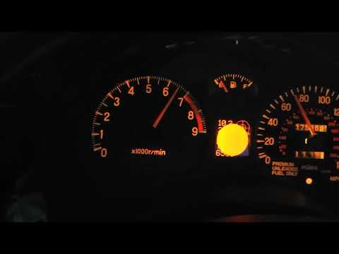
Right now you can use a web page to access the bluetooth interface of the board. It doesnt do much yet, but it can do firmware.
https://jamesoncollins.github.io/gauge_driver/web/webui.html
<img width="1000"alt="image" src="https://github.com/user-attachments/assets/8e128b6a-4ec2-453f-8a47-b11a5fabd94f" />
| Rev2 HW Feature | HW Status | SW Status | Rev1->Rev2 Changes | Notes |
|---|---|---|---|---|
| Analog input (4 channels) | Good enough | Not implemented. | 1st Order LPF | These ADCs are part of the microcontroller. Because of the type of converter these are I have to pick a specific bandwidth. I don't know what that should be, but I think no more than 100Hz. |
| Analog Output (1 channel) | Good enough | Tested, works. | Changed to SPI-based DAC. Higher power output OpAmp. | |
| Speaker | Good Enough | Working shift-alert | Louder speaker. | |
| Stepper Motors | Good | Fix minor layout issues, but mostly nothing. | ||
| Idiot Lights | Good (Not all lights supported) | Good | Comparator-based inputs to fix Battery warning light. | Haven't implemented Anti-Lock, Tour, Cruise, and ACS. |
| Accelerometer | Good | Good | None | |
| ECU Interface | Good | Good | None | Works with either ODB2 or MUT3, both using K-line. I have a chromed 93 ecu, that's the only thing tested. MUT3 is faster, 400sps when the engine isn't running and ~200sps with the engine running. It's not clear why there is a difference but I assume that the ECU control loop must use more processing time when running, and I also assume that I am supposed to limit the request rate anyway as according to some spec. This is true for ODB2 so I assume its true for MUT3, but I don't have the spec. |
| Bluetooth | Good | Basic demo interface | None | Possible uses: user input, android auto display of real-time ECU data, wireless firmware updates, log offloading |
| USB | Good | Good | None | USB support is part of the microcontroller. Currently it can be used as a virtual serial port, so it could be used for wired communication to a PC. |
| Screen | Good | Good | Fixed LCD pinout, changed OLED power supply to higher power chip. Add zeners to OLED as in data sheet. | |
| uSD Card and onboard flash | not tested | not tested | None | I assumed this would be used for datalogging. |
| Battery Backup | Good | Good | None | The board runs off battery power and uses an ignition signal to turn on. The board zeros the needles at shutdown and it tracks whether battery power is removed. If battery power is lost then the next boot of the board will come up in reset mode which will manually zero the needles. Its makes an ugly noise, and it takes time, so we go out of our way to avoid that. |
| External User Control | None | None | None | Currently there is no way to control the board at runtime. There are no buttons. You could rigup buttons to the IO. You could add some input panel via I2C. One idea might be to hijack the steering wheel controls (either radio, or cruise). We could also use bluetooth (but... ew...), or the USB serial connection. |
| Screen Mounting | N/A | N/A | 3d-printed mount | 3d-printed mount fits into the center cluster after milling away 0.6". You can still manually fit the screen board, it's just a bit of an art. |
| 12V inputs | Good | Good | No plans | There are a number of 12v (well, more than 12v...) tolerant digital inputs. |
| 12V Outputs | Good | Good | Added 400mA solid state relays. | These are not actually 12v outputs, they are bi-directional solid state relays. You can use them to switch small loads. |
| External I2C | Good | Good | Added QWIIC connector pads | These connectors are non populated by default. |
- Install a row of headers above and below the SSR pins to allow the relays to be attached to a voltage rail
- Install 250-400mA PTC fuse to supply SSR power
- Insufficient clearance for SSR header, it hits the speedo assembly. It either needs to be curved 90d or moved entirely.
- Support the remainder of the warning bulbs ( Anti-Lock, Tour, Cruise, and ACS ). Need to determine the type of inputs these are. If they are simple switches (like Brake) then we can just populate 4 more channels for clamping diodes.
Note, also check CHANGELOG in repo for additional TODO entries.