Final Project for ME314
NOTE:
This code was written in jupyter notebooks. To use, please clone this repository and open a terminal and run jupyter notebook then navigate to your local repository where you saved this code.
This project entailed simulating a planar multi-body, multi-impact dynamic system for which I chose to model a jack-in-a-box. Given that both the jack and the box have mass and the box also experiences an external force, I calculated multiple rigid body tranformations to find the Euler-Lagrange equations, dynamic constraints, and impact update laws.
In my model, I imagined a "bird's-eye-view" of the system, meaning the system lies on the x-y plane of an imaginary table and the z axis (which experiences gravity) is out of the plane.
See the images below for a drawing of the system and its components with all of the frames. There are 11 frames in total:
- W: The inertia frame W (Shown in all images in bottom left)
- B0: The frame at the center of the box (Shown in images 1 and 3)
- b1, b2, b3, and b4: the frames at each corner of the box (Shown in images 1 and 3)
- J0: the frame at the center of the jack (Shown in images 2 and 3)
- j1, j2, j3, and j4: the frames at each corner of the jack (Shown in images 2 and 3)
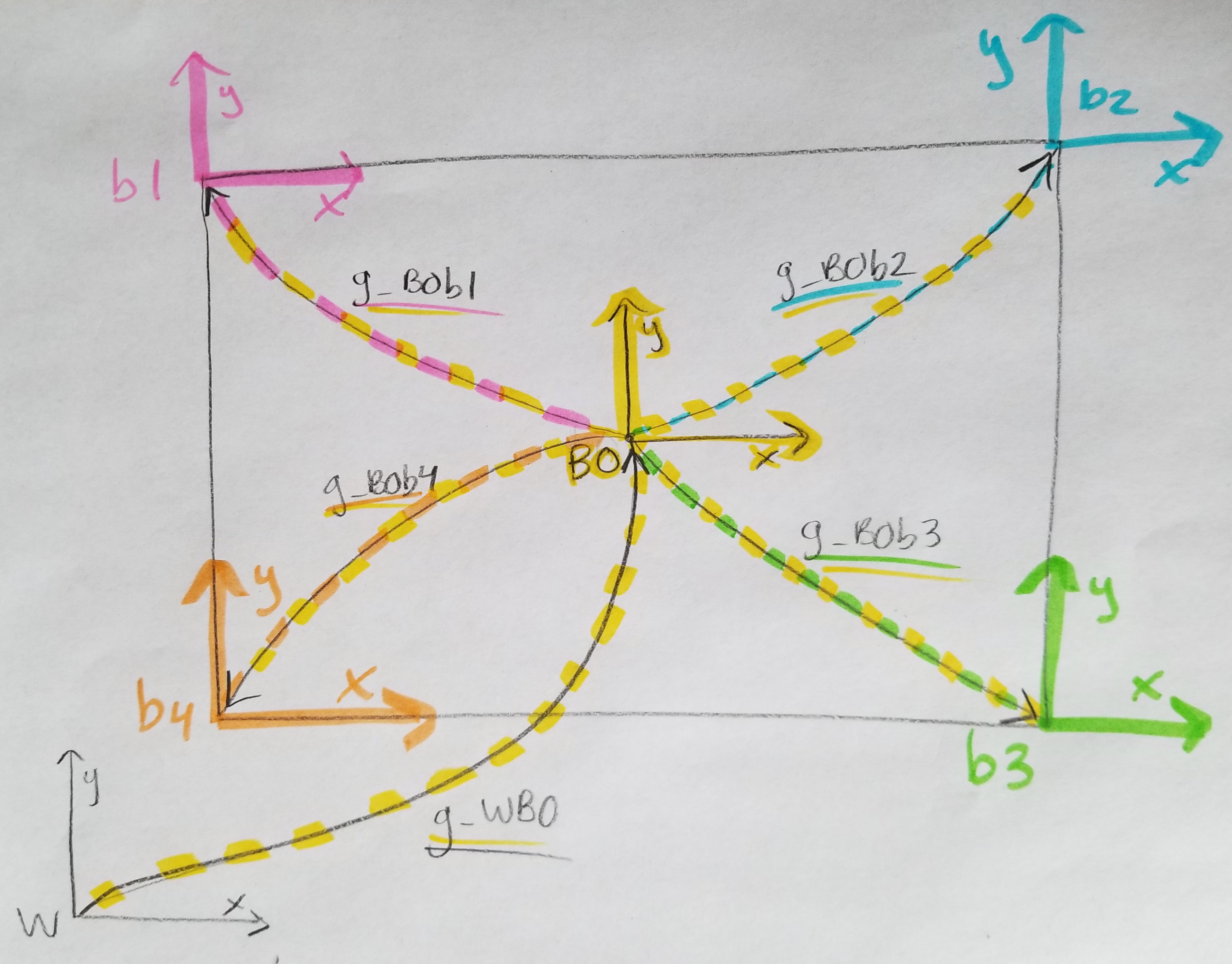 Image 1: Box diagram of frames and transformations
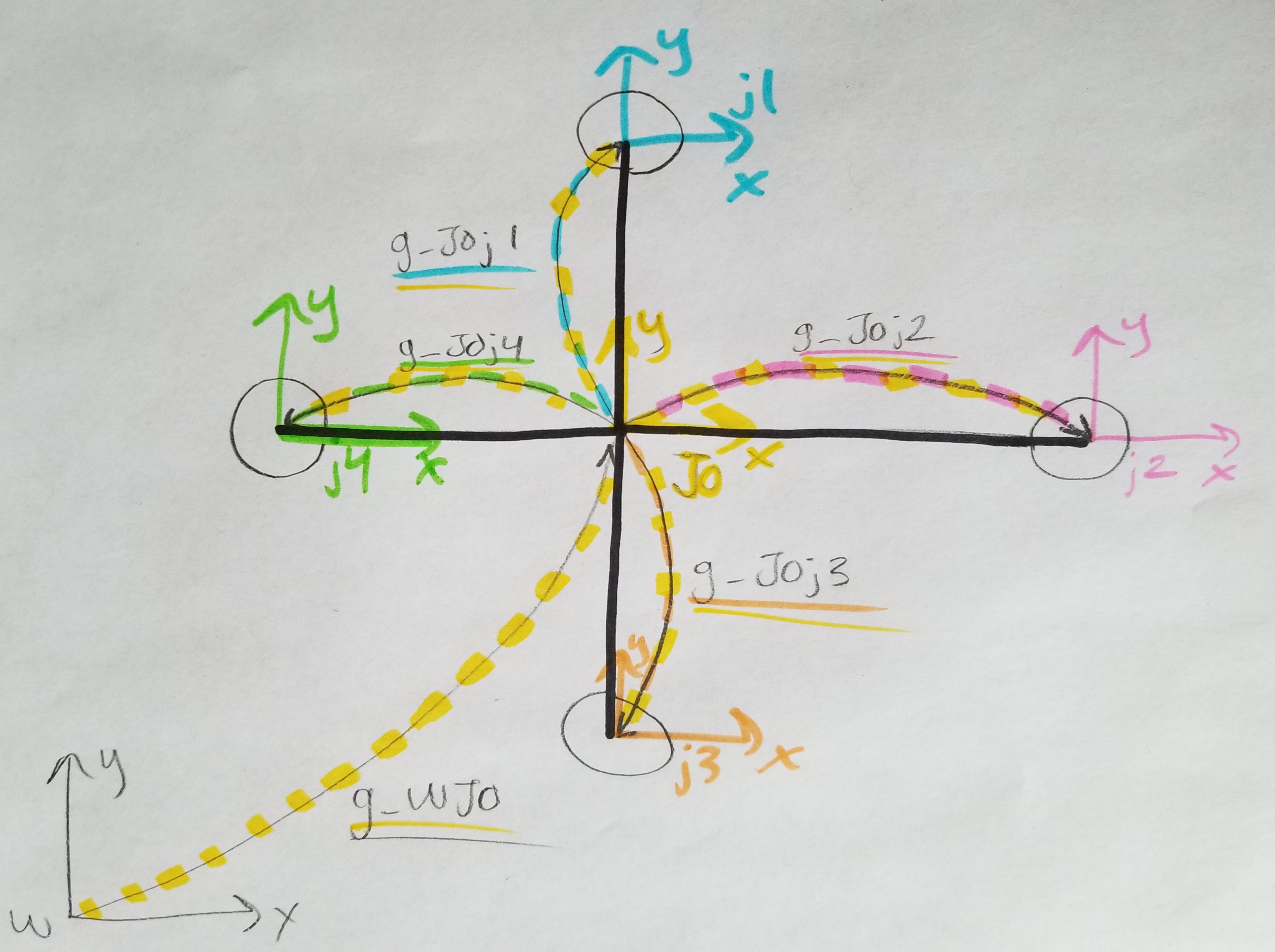 Image 2: Jack diagram of frames and transformations
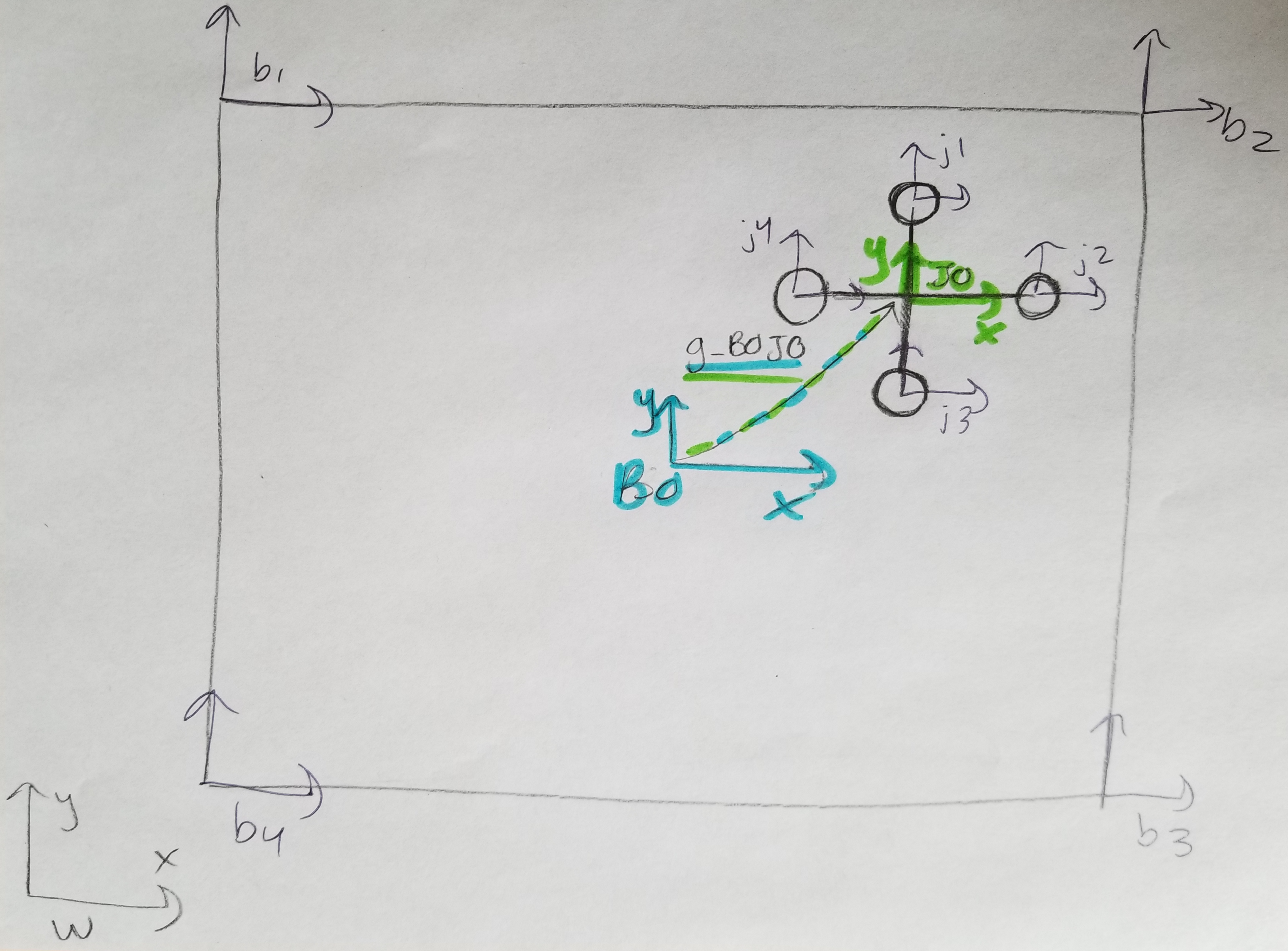 Image 3: Total System diagram (all frames and one transform)
The rigid body transforms between frames (shown above) are as follows:
- g_WB0 & g_WJ0: Transforms from W to the center of the box and jack respectively
- g_B0b1 - g_B0b4 : Transforms from the center of the box to each corner of the box. Initially, b1 is the top left corner, b2 is the top right, b3 is the bottom right and b4 is the bottom left.
- g_J0j1 - g_J0j4 : Transforms from the center of the jack to each “point” of the jack. Here, j1 is the top point, j2 is the right point, j3 is the bottom point and j4 is the left point.
- g_B0J0: Transforms from the center of the box to the center of the jack
- g_b1j1 - g_b1j4: Transforms from the box corner 1 to each point on the jack
- g_b2j1 - g_b2j4: Transforms from the box corner 2 to each point on the jack
- g_b3j1 - g_b3j4: Transforms from the box corner 3 to each point on the jack
- g_b4j1 - g_b4j4: Transforms from the box corner 4 to each point on the jack
From the transforms, I was able to determine the impact constraints for each point on the jack relative to each side of the box.
- For box corners 1 and 3, the impact is constrained by the y axis. Therefore the phi variable for these impacts is derived from the y translation component of the box corner to jack point transform. For example: phi_b1j1 = g_b1j1[1,3]
- For box corners 2 and 4, the impact is constrained by the x axis. Therefore the phi variable for these impacts is derived from the x translation component of the box corner to jack point transform. For example: phi_b2j1 = g_b2j1[0,3]
For my external force, I wanted the box to oscillate along the x axis (from side to side), so I used a sine wave with a period of πt and an amplitude of 700. This amplitude was determined after some testing. Therefore, the force equation is F_x = 700sin(π*t) and it is the first and only non zero entry on the external force matrix. This way the force corresponds to the xbox configuration variable in the Euler–Lagrange equation.
In order to calculate the Euler Lagrange equation, I first had to determine the Lagrangian (L = KE - PE). For that, I needed the rotational Kinetic Energy equation that utilizes the inertia tensor and body velocity (since we are not just dealing with point masses and therefore have rotational inertia). I calculated the body velocities for both objects, using the transforms from the world to center frames, since that’s where the center of mass is. (I made a square box and “square” jack). To find the box’s body velocity, for example, I calculated the inverse transform from the interia frame to the box’s center frame (g_WB0-1) as well as the derivative of the transform g_WB0. Multiplying the two, g_WB0-1 * d(g_WB0), I got the hatted body velocity (Vb_box_hat). After unhatting it, I was able to use the box body velocity (Vb_box) in the rotational KE equation.
I defined the box and jack to have point masses at each corner, so after calculating the entire mass for each object (mb_tot & mj_tot) and the distance the point masses were from the center (mb_dist, mj_dist), I was able to write the inertia tensor for both the box and jack (I_box & I_jack). The inertia tensor is 6 by 6 diagonal matrix with the components (m, m, m, J1, J2, J3), where J3 = (4 * point_mass * mass_dist) for both the box and jack (J1 and J2 are zero since we are not rotating about the x or y axis). With the body velocity and inertia tensor for the box and jack, I could calculate the rotational KE for both and sum them together to get the system’s total KE. Considering there is no PE since gravity is into the plane, the Lagrangian was simply the total KE. Taking the Jacobian of the Lagrangian matrix twice, I was able to calculate the left hand side of the E-L equations (ddL_ddq - dL_dq). I set the right hand side of the equation to be the external force matrix. Setting both sides equal to each other, I was able to solve the E-L equations for q_ddot for each configuration variable.
In order to calculate the impact update laws, first I split the E-L q_ddot solutions into separate configuration equations and assigned those their own lambdify functions. I then created dummy variables to use as q(tau-), combined all my impact constraints into one phi matrix and calculated the symbolic momentum and energy update for tau- (aka dLdqdot_sym, dphidq_sym and H_sym). Then, using the symbolic representation of tau+, I calculated the symbolic update equations for q(tau+) (dLdqdot_Plus, dphidq_Plus and H_Plus). I then determined the matrix for all the impact update solutions by subtracting the tau- momentum update by the tau+ momentum update for each configuration variable, as well as taking the difference in energy update equations. This is the left hand side of the impact equations. For the right hand side of the impact equations, I multiplied a symbolic lambda by each configuration component of the gradient of impact constraint matrix, dphidq_sym. I then set both sides equal to each other and solved for the impact updates.