Kailey Smith
The goal of this project was to design, construct, and control a small wheeled robot, completely from scratch. Dr. Malcolm MacIver’s lab is studying robot-rodent interactions and required a robot to act as a high-speed predator that will constantly try to discover, chase, and corner a mouse in a maze-like habitat.
To achieve this, I drew knowledge from my previous mechatronics experience to build a motor control circuit, communicate wirelessly using a Digi XBee module radio, as well as create a custom PCB. I also took inspiration from the Half-Sized Micromouse Competition for both mechanical and electrical design.
The end result: a remote controlled differential drive robot. Below is a video of robot being given left and right DC commands. It shows the robot moving forward and backwards, turning in a circle, and lastly moving in a loop. Note: these are only feed-forward commands, feed-back control is needed for precise movement.
Please checkout my portfolio post for more details.

MPLAB: Contains all C code, including programs used during breadboard testing and PCB testing.
Micromouse_solidworks_assembly: 3D modeled parts and assemblies.
Motor_Analysis: Contains a jupyter notebook in which I analyized different motors to use for the robot.
PCB_design: Contains all Eagle files, including libraries used and schematics/board desings
My goal was to create a simulated “race” between a given brushed DC motor and the mice to find motors that ran faster than the mice. Dr. MaIver’s lab provided me with mouse trajectory and velocity data over time from their ongoing experiments. With this information to compare to, I needed to extrapolate equations to calculate a motor’s position and linear velocity over time given only a motor’s electrical specs.
To model the motor’s behavior, I started using a simple equation that expresses input and outputs in terms of power below:
Where I is the current through the motor, V is the voltage across the motor, and
stand for torque and angular velocity on the output shaft and R is the motor’s internal resistance. The left side of the equation accounts for the electrical input power into a motor, while the right side accounts for the mechanical output power and power expelled through heat dissipation. After substituting in the torque constant
, then
for torque, and
for omega, I solved for an equation that is represented by the 1st and 2nd and 1st order differentials of displacement over time:
Once I had a function that was dependent on displacement over time, I was able to run the “race” simualtions. In order to get the robots linear and velocity displacement over time to compare to they mice, solved the equation for x(t) as well as x'(t):
Using the equations, I compared several motors to the mice by creating graphs such as the two below. The blue line represents the motor’s data while the green line represents a mouse.
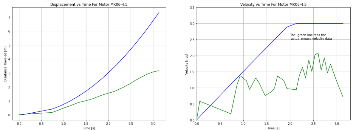
I also examined each motor’s torque-speed curve to ensure that a motor’s anticipated torque outputs were within the continuous operating region of that motor. Using all graphs I was able to eliminate several motors while still having a couple of viable motors to choose from.
My final motor selection came down to weight and size. For this entire system, the motors and battery we’re the largest and heaviest components. Therefore I wanted the smallest and lightest option of both. This meant choosing a 1 cell battery and therefore a motor that only needed up to 3.7V to operate. After doing some initial mechanical modeling, I chose a light and small motor that fit the design configuration I was looking for.
Once the critical parts were chosen, it was time to order all the other circuit components so I could start breadboarding and testing the circuit before ordering a custom PCB. I chose to use a PIC32 microcontroller since I had previous experience with these chips and there were a couple on hand to get started with quickly. Along those lines, I also chose to use the TI DRV8833 motor drivers. As a safety precaution, I added IR distance sensors to detect objects and avoid collisions. The last key component to this circuit was the Digi XBee 3 802.15.4 module which I used to communicate wirelessly with the robot.
In order to integrate all the circuit components into a small area on the robot, a custom PCB was necessary. After I confirmed that my circuit worked on the breadboard, I had confidence that I could design a functional PCB.
My initial thought was to use the PCB as a chassis component, as many of the Micromouse robots do. However, the MacIver lab uses a camera system above their habitat to track the mice and robot. And in order to detect, track, and determine the orientation of the robot, 3 red LEDs need to form an isosceles triangle on top of the robot. Given that, it was simple to rework the mechanical design so the PCB was the top-most component.
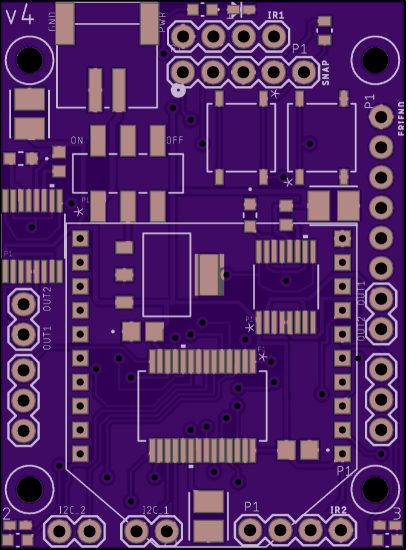
As with all PCB prototyping, this was a very iterative process, especially considering how many components needed to fit in such a small space. The dimensions of the PCB were determined by the footprint of the robot, which in turn was driven by the length of the motors. I was able to fit 35 components in a 46cm x 34cm space as pictured below.
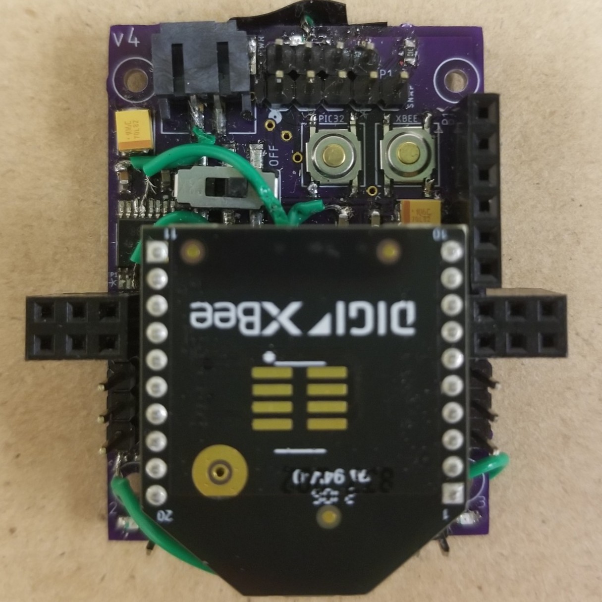
Once the boards were manufactured, I soldered all the individual components myself using a microscope. I quickly realized I couldn’t program my microcontroller. I did a continuity test to identify the issue and discovered I didn’t have common ground across all the components. To get my PCB up and running as quickly as possible, I soldered jumper wires to all components that needed common ground. After that I was able to program the PIC and confirm that all my other connections were correct. I designed a new board with common ground for future use.
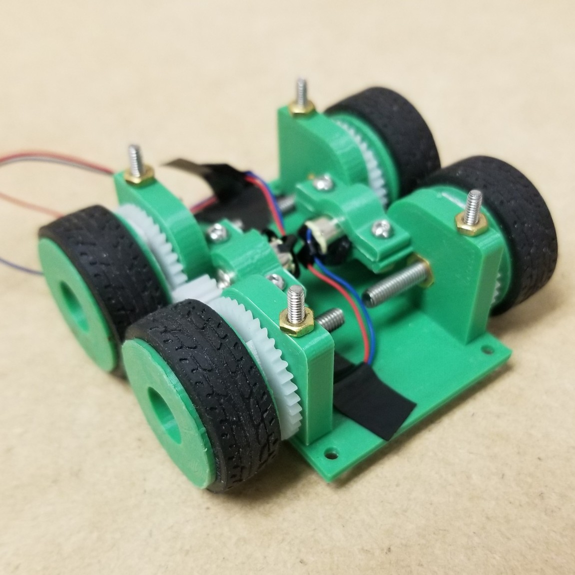
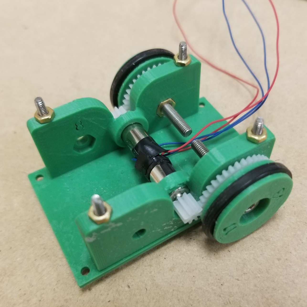
Below are images of the finalized, differential drive robot that I modeled in Soldiworks and then 3D printed.
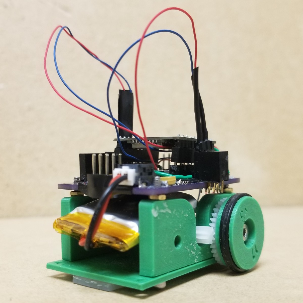
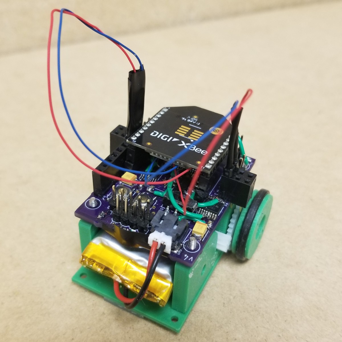
I started with a four wheel configuration like many of the Micromouse designs. But after some testing, I discovered that the flooring in the MacIver lab habitat has a much higher coefficient of friction than the flooring used in the Micromouse competitions. I decided to remove two wheels and switch the tire material to a harder rubber o-ring which were skinner and therefore had smaller areas of contact to make turns easier. The thinner wheels also had the benefit of making the overall width of the robot smaller.
As a safety feature the next immediate step will be incorporating the IR distance sensors as object avoidance / collision detection. I have already accounted for the sensors in my PCB, so all there is left to do is mount the hardware and implement functionality onto the microchip such that the robot stops if it senses that an object is too close.
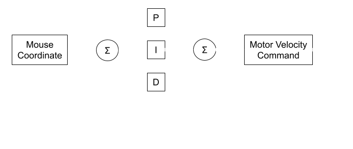
Given that there is a mechanically and electrically sound design, the next control steps are to add a PID controller. The MacIver lab is able to track the robot's location as it moves throughout the habitat. With that information, a position feedback controller can be implemented per the block diagram below.
Once the PID controller is squared away, the final step for autonomous navigation will be to create a path planning algotihm. This algorithm will recevice a mouse location and plan a route from the robot's location to the mouse while avoiding all obstacles. With that, the predator robot will be fully operational! Final Project for MSR program at Northwestern.