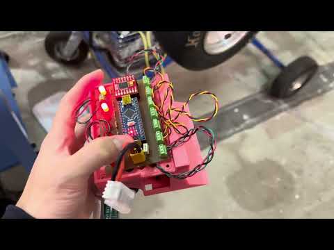
Two weeks - that was the time I had to go from absolutely nothing to a fully-functioning robot to participate in the upcoming competition in Orlando, Florida. At the time, it took JLCPCB 4 weeks to ship a PCB to the US even with rushed shipping due to delayed customs; so, I decided to make everything inside our makerspace - The Hive.

Thanks to my wonderful peers and the knowledge gained throughout my time at Georgia Tech, I learned how to use KiCAD, fabricate the PCB using the LPKF Protomat/Protolaser, and through-hole solder all the components. The chassis of the robot was designed by a wonderful teammate on the mechanical side. This version was merely a rushed proof of concept for the upcoming competition (if you read on, you will see the various limitations I faced and how I combatted them for the time being). A significantly more complex, 4-layer PCB that addressed all the issues along with quality of life updates have been created the following semester: SumoBot v2!
Since I only had two weeks, my goal was to add only the bare minimum components for a functional robot. This consisted of a distance sensor to detect the other sumobot, a line sensor to detect whether we were out of bounds or not, a motor driver to drive the wheels, a power system, and status LEDs for debugging. The arduino nano was small and sufficient for my needs; here is my very first schematic:

With the distance sensors and line sensors being abstracted as an attachable module, it was easy to determine which footprints to use since it was either a screw terminal to attach said sensors or female pins to insert the arduino and the motor driver. However, the only issue was power. While I could have used a buck converter, I figured for simplicity sake, I would use a MOSFET that basically dissipated excess voltage into heat, allowing it to supply 5V to the entire system. The advantage here was that I could actually connect the battery's 9V directly into the motors so that while the system got the 5V it needed, the motors could go overdrive at 9V.

This is where I ran into my first issue: as simple as the Arduino Nano was to use, if I hogged 7 pins for status LEDs (5 for distance and 2 for line), I ran out of GPIO pins to use for the motor driver. Considering I had two weeks left, I did not have a time to come up with a complex strategy. So, I just tied AI1 and BI1 to 5V and AI2 and BI2 to GND (along with STBY to 5V), which saved me THREE pins. The only drawback was the fact that I could not move backwards; however, depending on the values of PWMA (left motor) and PWMB (right motor), I could control the speed and spin around as needed.

While I found it super cool that I could literally fabricate a PCB inside our makerspace, I soon figured out why nobody actually used the machines: it was plagued with a lot of limitations and lack of experience. Considering the fact that none of the peer instructors (other than one passionate master PI who I cannot thank enough) knew how to use the machines and I only had a book to go off of, I ran into a lot of minor inconveniences and setbacks. However, I will filter out the noise and only highlight the limitations of the final product (i.e. I won't get into nontechnical issues such as alignment as shown below):

While the LPKF Protomat and Protolaser could technically make a functional PCB, there was no way to make vias (non-plated drilling). In other words, I could not connect the front layer to the back layer unless I manually connected them via soldering both sides with a wire, which turned out to be a very big inconvenience. So, I had to connect all my traces from VCC to GND to all GPIO pins into the back layer so that when I through-hole soldered everything, the objects would be on the top layer and the soldering will all be done on the bottom layer. Keep in mind, the places where I placed screw terminals and female connectors pins were physically obstructed by the object itself, so if I ever wanted to connect layer 1 to layer 2, I had to create vias to the side, as shown in one of my failed iterations:

Now you may be wondering: aren't PCBs usually green? Well, that's because my PCBs lacked a solder mask since our makerspace did not have a machine to create them; that also included silkscreens so I had to physically laser out the copper using the laser of the LPKF Protolaser for any text. This made it an absolute nightmare for continuity testing because I kept getting shorts to the GND plane, which was on the same layer as all my connections.

This is more of an advanced topic that didn't detrimentally affect the robot, but considering my PCB virtually had zero decoupling capacitors and no dedicated power planes, the whole power network was more susceptible to power supply noise and EMI. Luckily, I did create a ground pour on the unused area and tried to connect a few wires into the other layer for a giant GND plane for heat dissipation on the motors, it was by no means optimal. This issue was fixed during my second iteration in SumoBot v2, but this really was just a proof of concept in the end. Not to mention, 90 degrees traces weren't exactly good practice due to impedance discontinuities, while negligible for my use robot:

Also, A7 is an analog input only pin. While it doesn't affect functionality, you would not see the LED flash.
Now fabrication is actually very simple: you import you gerber files (front layer copper layout, back layer copper layout, edge cuts, and drill files) and use the LPKF Protomat to drill the holes:

Then you remove the unwanted copper using the LPKF Protolaser:

And back to the LPKF Protomat to cut out the board itself from the bigger sheet of copper:

Thanks to many failed iterations that allowed me to practice soldering, I was able to complete the board! With careful continuity testing, it was ready to be mounted onto the mechanical chassis.

Our makerspace had a plethora of 3D printers. One freshman mechanical teammate was diligent and ambitious enough to create the chassis for us in the limited time that we had; here is are a few pictures:


Due to it being a public repository, I have only included the basic code for a functional robot. Complex state machines and algorithms used during the competition are excluded.
While we were a group of five, the whole robot was essentially created by me and the mechanical teammate. Here is a working demo of our robot with my functional PCB: