
A crosshair-driven explorer for a T1 brain MRI. Move one plane through the head; the three axis slices, the oblique cut and the raymarched volume all follow the same point. Plan a trajectory and it reports the depth in patient millimetres and whether the track crosses a vessel.


-informational)
| Walkthrough |
|---|
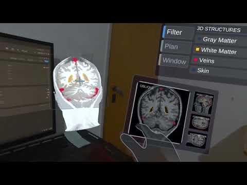 |
| Slices, structures, trajectory planning and the intensity window, on a Quest 3S |
Windows executable and Quest APK: Google Drive
Run Synav.exe on desktop, or sideload Synav.apk with adb install -r Synav.apk. Neither needs the project or the editor.
A scan is three stacks of images and a pile of segmented surfaces, and most viewers make you drive them separately: one slider per axis, a 3D view in its own mode, meshes sitting beside the scan. That works for reading a study. It works badly for planning, because planning is a question about a point: what is here, what surrounds it, and can I reach it without crossing something.
So the app holds one piece of state: the pose of a plane you pick up and move. Every view is a readout of that single transform, so no two of them can disagree.
Segmentation is rasterized into the scan's own voxel grid. That turns "is there a vessel here" into an array lookup, and it lets one set of data colour the 3D render, tint every 2D slice, and answer the corridor check.
- Renders the IXI025 T1 MRI (256 x 256 x 150) as a raymarched volume
- Reslices the grid into axial, coronal and sagittal images that follow the crosshair, each labelled with its slice index
- Cuts the volume with a plane you can move and rotate, and shows that oblique slice as a fourth image
- Keeps the cut facing you, so turning the plane never buries the exposed face
- Carries skin, gray matter, white matter and veins as labelled voxels inside the scan, coloured in the volume and tinted into every slice, each toggled from a menu
- Plans a straight entry-to-target trajectory, reporting depth in patient millimetres and warning when the track crosses vessel voxels
- Pins the entry point to the scalp and lets you slide it over the skull to hunt for a clear approach
- Windows the volume by intensity, with air excluded whatever the sliders say
- Runs on desktop with mouse and keyboard, or on a Quest with hand tracking, from one scene
flowchart LR
  M[4 structure meshes] --> Z[StructureVoxelizer<br/>rasterize to label grid]
  Z --> L[Label volume<br/>one id per voxel]
  P[Section plane<br/>grab and move] --> C[Crosshair<br/>plane centre]
  C --> V[VolumeSampler<br/>world to voxel]
  L --> V
  V --> A[Axial slice]
  V --> K[Coronal slice]
  V --> S[Sagittal slice]
  P --> O[Oblique reslice<br/>192 x 192]
  P --> X[CutoutBox<br/>cuts the volume]
  L --> G[Coloured voxels<br/>in the volume]
  O --> B[MPR board]
  A --> B
  K --> B
  S --> B
  C --> T[Trajectory planner<br/>entry / target markers]
  T --> D[Depth, mm]
  T --> N[Corridor vs vessel voxels]
  L --> N
Everything that touches voxels goes through VolumeSampler. UnityVolumeRendering draws the dataset into a unit cube spanning -0.5 to 0.5 in its own local space. A world point becomes a texture coordinate by inverse-transforming it into that cube and shifting by half a unit:
Vector3 local = cube.InverseTransformPoint(world);
uvw = local + Vector3.one * 0.5f;          // 0..1 across the volume
voxel = Vector3Int.FloorToInt(uvw * dims); // dims = (256, 256, 150)
Keeping that in one class holds the slices, the cut and the volume on the same coordinates, and it is where the labels plug in: an intensity lookup and a label lookup at the same world position always land on the same voxel. A registered atlas would plug in through the same class later.
MprScreens fills the axial, coronal and sagittal panels from the voxel under the crosshair. The dataset is 256 x 256 x 150, so axial comes out 256 x 256 and the other two 256 x 150.
Panels are sized in millimetres. IXI025 voxels are 0.9375 x 0.9375 x 1.2 mm, so the scan measures 240 x 240 x 180 mm: coronal and sagittal come out 4:3, axial square, and the head keeps its proportions in every view.
Intensity maps straight to grey, tinted toward a structure's colour where one is labelled. Tinting keeps the underlying intensities readable, which is the point of looking at a slice. The transfer function only shapes the 3D volume. It never touches the 2D slices, which stay a straight readout of intensity.
Each panel prints its slice index the way a clinical viewer prints an image number, one-based out of the stack depth. Nothing here is a stored image, so the number is the reslice index along the axis that view cuts across.
The section plane carries a UnityVolumeRendering CutoutBox sized to its own rectangle. The box clears the volume inside that rectangle and leaves the rest of the head standing, so the cut reads as a window opened into it.
The same plane is swept to produce the oblique image, stepping through the volume with the matrix from VolumeSampler:
Matrix4x4 toUVW = sampler.WorldToUVW * pose;
Vector3 rowStart   = toUVW.MultiplyPoint3x4(new Vector3(-planeSize * 0.5f, -planeSize * 0.5f, 0f));
Vector3 acrossStep = toUVW.MultiplyVector(new Vector3(step, 0f, 0f));
Vector3 downStep   = toUVW.MultiplyVector(new Vector3(0f, step, 0f));
The MPR board's fourth panel draws that same 192 x 192 texture; the 3D cut and the 2D oblique slice can never show different things. The cutout box also moves to whichever side of the plane you stand on each frame, keeping the open face toward you.
The four segmentation meshes are rasterized into a single label volume on the MRI's own grid, one integer id per voxel, and handed to UnityVolumeRendering as a secondary volume. The structures become part of the scan: they colour the raymarched volume, they tint every 2D slice, and they can be read per voxel.
The mapping needs no calibration. MeshesRoot carries the same transform as the volume container, so VolumeSampler.WorldToUVW takes a mesh vertex straight to the voxel it falls in. Every vein vertex lands in a vein voxel.
Reading a structure as voxels lets the trajectory check answer the surgical question directly: does this track pass through a vessel. A vessel is caught by the voxels it fills, at whatever thickness and wherever the track enters it.
One voxel holds one id, so overlaps resolve by write order and vessels are written last. Hiding a structure zeroes its colour. The data stays, so a vessel hidden from view still counts in the corridor check.
The bake depends only on the meshes and the grid, both fixed, so it is stored beside the scan as one gzipped byte per voxel and unpacked at startup.
TrajectoryPlanner captures entry and target from the crosshair on two button presses and draws a line between them. Depth comes back in patient millimetres through VolumeSampler.PatientDistanceMm, the distance an instrument would travel through the patient.
Both markers are children of the volume, so grabbing the head and turning it carries the markers, the line and the readout with it. Depth and the vein warning are patient-space measurements and do not change because the head was picked up.
An entry point only means anything on the surface, so setting one projects it onto the scalp. A ray from the head's centre marches the volume's intensity looking for the air-to-tissue boundary, working inward from outside the head. Marching that direction is what stops an internal air pocket, a sinus say, being taken for the exterior.
The safety corridor walks the track through the label volume, sampling the centre line and a ring of 8 offsets at the corridor radius:
for (int i = 0; i <= steps; i++)
{
    Vector3 p = entry + axis * ((float)i / steps);
    if (IsVein(p)) return (float)i / steps;          // straight through a vessel

    for (int k = 0; k < CorridorSamples; k++)        // and the sleeve around it
    {
        float a = k * Mathf.PI * 2f / CorridorSamples;
        if (IsVein(p + (across * Mathf.Cos(a) + up * Mathf.Sin(a)) * radiusWorld)) return (float)i / steps;
    }
}
A track driven through a vessel is a hit outright; the ring is what honours the corridor for a track that threads close by without touching. The radius converts through the track's own world-per-millimetre ratio, the same scale the depth readout uses, so the translucent tube drawn around the track is the tube being tested.
Neither input path talks to the tools. Both drive a Meta Interaction SDK RayInteractor, which needs two things: a transform to aim and an ISelector that says when a click happened. A hand ray supplies a wrist pose and a pinch; on desktop, MousePointer supplies a screen ray and a mouse button:
Ray ray = viewer.ScreenPointToRay(Input.mousePosition);
transform.SetPositionAndRotation(ray.origin, Quaternion.LookRotation(ray.direction));

if (Input.GetMouseButtonDown(0))
    WhenSelected?.Invoke();
Buttons, hover tints and menus all sit downstream of the interactor, and none of them can tell the two apart. DesktopMode picks the rig at startup: it starts on the headset whenever an XR loader is present, and falls back to desktop if the display never begins presenting.
Panels carry an inert RayInteractable over their whole face, which keeps the ray lit all the way across a panel as you travel between its buttons. On the MPR board that backdrop also carries MouseGrabExempt, so the images take a point while the rest of the panel takes a grab.
Level and width choose which intensities are drawn, the control a radiologist reaches for first. Narrowing the window raises contrast across whatever survives inside it; sliding the level walks that band up and down the tissue types.
Air stays excluded underneath both sliders, whatever they are set to. It is the darkest thing in the scan and there is nothing in it to see.
float half = width * 0.5f;
VisibleMin = Mathf.Max(airFloor, level - half);   // airFloor = 0.01
VisibleMax = Mathf.Max(VisibleMin + 0.01f, Mathf.Min(1f, level + half));
volume.SetVisibilityWindow(VisibleMin, VisibleMax);
The floor costs 0.4% of vein voxels, vessels sitting at intensities below it.
- Engine: Unity 6000.4.0f1, Built-in render pipeline, C#
- Volume rendering: UnityVolumeRendering (raymarched DVR, 256 steps per ray, secondary volume for the labels)
- Data: IXI025 T1 MRI as NIfTI (
.nii.gz), 4 co-registered.objsegmentation meshes, baked label volume as a gzipped.bytesasset - XR: Meta XR All-in-One SDK over OpenXR, Single Pass Instanced stereo, hand tracking through the Interaction SDK
- Builds: Windows x64 (D3D11) and Quest standalone (Android, IL2CPP, ARM64, Vulkan)
IXI025 from the IXI brain-development set, a T1-weighted head MRI:
dimensions   256 x 256 x 150 voxels
spacing      0.9375 x 0.9375 x 1.2 mm
extent       240 x 240 x 180 mm
format       NIfTI-1 (.nii.gz), single channel, RHalf on the GPU
Four segmentation meshes ship alongside it, already in the scan's frame: skin, gray matter, white matter, veins. StructureVoxelizer rasterizes them into one label field on the same grid:
id 0  background      id 2  gray matter
id 1  veins           id 3  white matter
                      id 4  skin
One byte per voxel, 9,830,400 voxels, gzipped to 353 KB. Overlaps resolve by write order, vessels last, so a voxel that is both vein and white matter reads as vein, the conservative answer for a corridor check.
Run the executable, or open the project in Unity 6000.4.0f1, open Assets/NavianChallenge/Scenes/NavianChallenge_Main.unity and press Play. No headset needed.
| Input | Action |
|---|---|
| Right-drag | Look around |
| W A S D | Move |
| Q / E | Down / up |
| Shift | Move faster |
| Wheel | Forward / back |
| Arrow keys | Angle the cut plane |
| Left-click | Press a button |
| Left-drag | Move a panel or the head |
| Wheel while dragging | Push away / pull closer |
| Shift while dragging | Rotate instead of move |
| F | Reset the view |
| H | Hide the on-screen controls |
Start by dragging the section plane into the head; the oblique panel is black until the plane meets the volume. The Plan tab holds the trajectory tool, Filter the structure toggles, Window the intensity sliders.
Turn your left palm towards your face for the wrist menu, which shows and hides the three tools. Buttons take a poke or a point and pinch. Panels are grabbed by their frame; the images inside take a point. Link works too: connect the headset, start Link, then press Play in the editor.
Built-in pipeline, one scene in the build list. Desktop targets Windows x64 and opens windowed at 1600 x 900. The headset build targets Android with IL2CPP, ARM64 and Vulkan. The two are written side by side and share nothing but the scene.
Slices sample nearest-neighbour. A slice is a texture lookup per pixel and the volume is 150 slices deep, so nearest neighbour is fast and honest about the source resolution. Images do go blocky when a panel is pushed close to your face.
Structures are labelled voxels. A label volume answers "what is at this point" for any point, which is what both the corridor check and the slice tinting need. Both read the same array by index.
The corridor is measured in patient millimetres. Voxels are anisotropic at 0.9375 x 0.9375 x 1.2 mm, so the radius converts through the voxel spacing and covers the same true distance whichever way the track runs.
Structure colours are chosen against a greyscale base. The scan spends the whole lightness range on anatomy, so chroma is the only channel left to separate a label from tissue. Gray and white matter border each other everywhere, so they take opposing warm and cool hues while keeping the relationship that distinguishes them on a T1: white matter is the brighter of the two.
Two colour systems, kept apart. The axial/coronal/sagittal frames use the radiology convention, green/red/blue, and the structure and safety colours are anatomical and status colours, left where a clinician expects to find them. Panel chrome uses a separate navy/steel palette that never touches those.
Assets/NavianChallenge/
  Scenes/NavianChallenge_Main.unity   the whole app
  Data/Atlas/IXI025/                  MRI (.nii.gz) + 4 segmentation meshes
    Labels/StructureLabels.bytes      the baked label volume, rebuilt if deleted
  Scripts/
    Core/                             works the same regardless of input rig
      VolumeSampler.cs                 world to voxel, the shared coordinate map
      SectionPlane.cs                  binds the cutout, reslices the oblique image
      MprScreens.cs                    the three axis slices + the shared oblique texture
      TrajectoryPlanner.cs             entry/target depth and the corridor check
      DraggableEntry.cs                holds the entry marker on the scalp while dragged
      StructureVoxelizer.cs            rasterizes the meshes into the label volume
      StructureToggles.cs              structure visibility
      WindowLevel.cs                   window and level, air always excluded
      WindowLevelSlider.cs             the two sliders that drive it
      CorridorSlider.cs                drag slider for the corridor diameter
      VolumeStyle.cs                   transfer function applied at runtime
      AtlasVolumeLoader.cs             builds the MRI volume at runtime
    UI/                               interaction primitives both rigs consume
      MainMenu.cs                      sectioned menu, rail left, content right
      ButtonSignal.cs                  one press event from poke or ray
      DragSlider.cs                    drag behaviour shared by the panel sliders
    Desktop/                          only meaningful without a headset
      DesktopMode.cs                   picks the rig at startup
      DesktopViewer.cs                 desktop camera and on-screen controls
      MousePointer.cs                  screen ray + click, as an ISelector
      MouseGrab.cs                     press and drag panels with the mouse
      MouseGrabExempt.cs               marks a surface MouseGrab should never pick up
      PlaneRotateInput.cs              arrow keys angle the cut plane
    XR/                               only meaningful with a headset
      WristMenu.cs                     shows and hides the three tools
      Foveation.cs                     lowers the resolution of the eye buffer's periphery
  Shaders/
    PanelFrame.shader                 SDF rounded frame, stereo instanced
    TrajectoryLine.shader             unlit line drawn on top of the anatomy
    TrajectoryRay.shader              per-vertex gradient along the track
  Editor/                             one-off scene-building tool, see note below
Assets/ThirdParty/UnityVolumeRendering/
Editor/ChallengeSceneBuilder.cs procedurally rebuilds AtlasRoot from the raw .obj/.nii.gz assets. Nothing in the workflow depends on it, and re-running it discards the alignment and any scene edits made since.
- You cannot click inside a 2D slice to move the crosshair. The panels are readouts only, so navigation is always through the plane. This is the largest gap against a real MPR viewer.
- No region naming. Structures are labelled, anatomical regions are not, so the app cannot name what sits under the crosshair. That needs a registered atlas, which this does not ship.
- The window does not reach the 2D slices. The volume honours it; the four images still map intensity straight to grey across the scan's full range.
- Reslicing runs on the main thread. A 192 x 192 oblique reslice recomputes on every plane move. It does not scale to a larger scan or a bigger panel.
- The GPU budget is unprofiled on device. The optimisations in the headset build are the standard ones for a fragment-bound load, chosen without a trace to point at.
- Structures render at the scan's resolution, so edges are 0.94 mm steps. Label ids cannot be interpolated: a value halfway between two ids is a third structure. The blockiness is the true resolution of the data.
- Click in a slice to move the crosshair. Cheapest item here and it closes the largest gap; the panels already know their own voxel mapping.
- Offline atlas registration. Register Harvard-Oxford into IXI025's native grid offline, in Python, with ANTsPy or SimpleITK doing the iterative fitting. The result is labels on the same affine plus a
regions.jsonof names, synonyms and centroids: the label-volume path already exists, and the JSON is a seam that lets registration quality improve later without touching app code. - An LLM agent to move the crosshair. With
regions.jsonin place, an agent resolves "show me the left ventricle" against region names, synonyms and descriptions, then moves the crosshair to the matched centroid. The interesting part is robust request understanding: matching synonyms, typos and compound descriptions against the names and synonyms already inregions.json. - Carry the window through to the 2D panels, with trilinear sampling, which is what makes slices readable in a clinical viewer.
- Profile the headset build, then decide between sampling rate, MSAA and texture bit depth against a real number.
- IXI dataset, Imperial College London
- UnityVolumeRendering, Matias Lavik
MIT.